I-Box 4.x
The ultimate distribution box for your component tests – integration and connections for up to 10 control units
The TESTERLYZER® I-Box 4.x is a modular power/signal distribution box and serves as the new centrepiece for your automotive component testing requirements. It provides all the necessary signals in the backbone, with distribution to standardized adaptor slots and interfaces for simple control unit connectivity.

CAN high

Ethernet

RS 485

RS 485

100 — 240 V

Remote

Sound

CE
Functionality
The basic version of the TESTERLYZER® I-Box 4.x offers the following features:
- Bus and voltage connections for 10 control units
- Display of the operation voltage (0–15.9 V; Resolution: 0.1 V ±5% + 1 digit of the displayed value)
- Display of the control unit power consumption, also standby consumption (0–15.999 A; Resolution: 1 mA, ±5% + 1 digit of the displayed value)
- Display of the terminal status (for terminal switching via control units / ECUs)
- Switching of 3x terminal voltages: manual or via connected ECUs or remote if compatible)
- Switching of the audio configuration
- Switching of the audio to Mute (on externally wired speaker or during load impedances)
- Joint switching of a terminal voltage for ECU 1.10 from internal to external voltage input (max. 16 V DC at 15 A)
- Activation of OBD
- Tapping of 6 CAN Buses (scheduled switching on front panel)
- Tapping of 10 serial interfaces (UART) on the front panel
- Ready for universal logger connection on device side for CAN buses and UARTs
- Power of control unit with internal power supply of up to 15 A
I-Box 4.x
Product inquiry
Call-back service
Downloads
Product inquiry
[contact-form-7 id=”3584″ title=”Produktanfrage”]
Call-back service
[contact-form-7 id=”3066″ title=”Rückrufservice”]
Downloads
- Brochure (PDF, 2,5 MB)
- Operating instructions (PDF, 8 MB / login required)
Your contact
Have you got questions about purchasing this product or would like technical support? We’re happy to provide personal advice and consultation!
#hassle-free-service #customer-care
Carsten Dörr
Jetzt anrufenBenefits
- Power supply and universal wiring distribution in a single device
- OEM-independent use
- Can be used as a stand-alone table setup solution or in connection with a rack setup
- Easy connectivity thanks to standardised plug
- Compact and tidy BASIS test environment
- RUETZ TECHNOLOGIES configures the modular connection adaptor according to the requirements of the system environment
- Individual adaptors are available for future upgrading measures
Areas of use
- Functionality tests of electronic control unites and qualification of ECUs
- Validation and verification of ECU hardware / firmware in the respective vehicle interior
- Integration and compatibility test of prototypes
- Generation of functionality documentation, instructions support for hotline services and service providers
- Training material, presentations
Expansion options
Remote control and additional features of the TESTERLYZER® I-Box 4.x thanks to a host computer connection.
01_Remote
The measurement data are transferred to a host computer or
an automation interface.
- Power and voltage measurement values, status of terminal remote-control functionalities: switching of internal/external voltage supply
- Activation of OBD
- Switching of terminals 30, 30f, 30b
- Audio configuration
02_RIO
(Remote I/O)
Remote control of freely assignable potential-free contacts and reading of freely assignable inputs on optocouplers.- Reading of 2×8 digital inputs via host computer
- Remote control of 2×8 digital outputs via host computer
03_CAN AS
(CAN Application Services)
- 4× keys on the I-Box 4.x for manual switching/triggering of freely definable CAN messages/sequences
- Status display on LED (predefined via script)
- Alive counter
- Checksum for securing the telegrams
- Additional CAN AS operational panel for expansion of the CAN capability, for triggering 100 additional freely definable CAN messages/sequences
04_V-DUT
- Remote control of the voltage supply for terminals 30, 30f, 30b of up to 4 test items by the host computer
- Manual operation via an additional optional key panel is possible
05_Operation panel
Optional control panel for displaying the digital inputs on LED and for manual switching of the digital outputs.
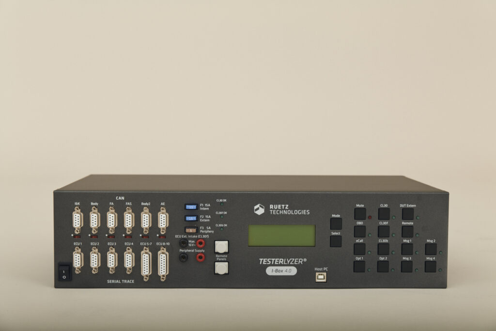
Equipment
Front (controls)
Front panel
- Main power switch (ON/OFF)
COMMUNICATIONS PANEL
- Tapping of 6 CAN buses (switchable termination)
- Tapping of 10 serial interfaces (UART)
Displaying and tapping of voltage supply
- Switching of terminals 30, 30f, 30b: manually via the control panel or via the connected EDUs, or remotely with the respective equipment
- External power input to 15 A for supplying terminal 30f, ECUs 1–10, switchable
- Automotive fuses
- LED status indicators
Display and menu keys
- Display of the operational voltage (0 … 15.9 V)
- Display of the control unit power consumption, also current of rest (0 … 15.999 A)
- Display of terminal status (for terminal switching using control units / ECUs)
Keypad control panel, incl. led status indicator
- Switching of terminals 30, 30f, 30b: manually via the control panel or the ECU, or remotely
- Switching of internal/external voltage
- Switching of the audio to Mute (on externally wired speaker or during load impedances)
- 2x optional switching functions, which can be defined and integrated according to the customer’s requirements (e.g. switching between Master/Slave or to the desired audio configuration)
- Activation of OBD
Host computer connection
- Serial USB connection for optional remote functionality
- Connectivity for additional control units via RJ45 jack (communication via RS485 bus)
Back (connectivity for control unit cable adaptors, loggers, speakers)
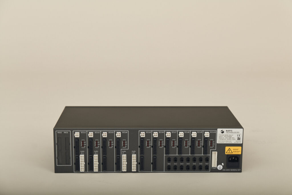
Cable adaptor connectivity for a total of 10 control units
The signals are distributed via the respective pin groups for bus, voltage and audio connections.Logger connection for CAN buses and UARTs
The pre-routed bus and data lines that have been wired internally in the TESTERLYZER® I-Box 4.x can be tapped at the logger connection. This enables fast and secure access to up to 5 trace lines and up to 6x CAN buses.ETH patch panel
7x patch panel for ECU 2-wire automotive ethernet data cable to allow a peer-to-peer connectionDigital I/O assembly
Switching of customer-specific loads (optional)Control unit connections on back panel
The user can define the signals and the corresponding pin assignment themselves, or we can contact your cable adaptor to predefined signals.- 10x 4-pole system for voltage supply [ECU 1 – 10]
- 10x 24-pole system for CAN and special signal conditioning [ECU 1 – 10]
- 4x 20-pole system for CAN and special signal conditioning [ECU 1 – 4]
- 2x 18-pole system for audio input [ECU 1 – 2]
- 1x 18-pole system for audio output [OEM-specific speaker system]
- 1x 18-pole system for audio impedance [OEM-specific values]
- 1x 34-pole system for CAN UART connection [OEM-specific media switch / converter / logger]
- 7x 2-pole ethernet patch field [ECU]
Optional extras
- 16x relays [switch of 3 A per contact, potential-free]
- 16x inputs, 0.5 A per pin, with optocouplers [potential-free]
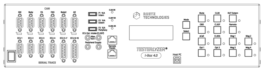
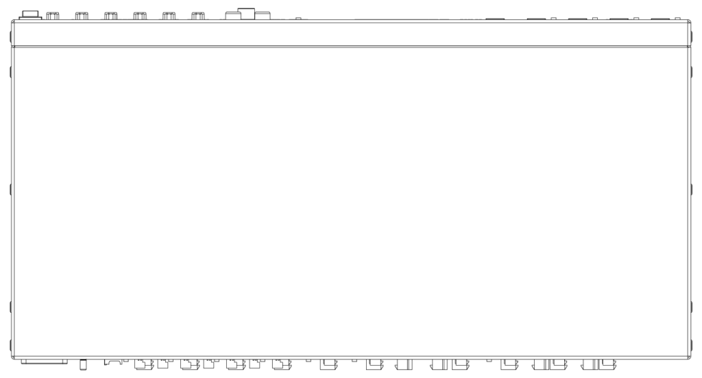
Dimensions
Front
Top
| Technische Daten | ||
|---|---|---|
|
Abmessungen B × H × T |
442 × 111 × 220 mm |
|
|
Gewicht |
5,4 kg |
|
|
Primärspannung |
100 — 240 V (50 — 60 Hz) |
|
|
Stromaufnahme |
4 A |
|
|
Leistungsaufnahme |
250 W |
|
|
Sekundärspannung |
13,2 V DC · abgesichert 15 A |
|
|
CAN-Busabgriffe |
6× Sub-D 9 |
|
|
Spannungsabgriffe |
1× Gerätespannung auf Bananenbuchsen (abgesichert 5 A) |
|
|
Externe Spannungseinspeisung |
0 — 16 V DC · extern abgesichert mit max. 15 A (30 f) |
|
|
Lüftung |
Temperaturgesteuerter Lüfter |
|
|
Schallpegel |
< 50 dB (A) |
|
|
Schutzklasse |
1 |
|
|
Schutzart |
IP 20 |
|
|
Luftfeuchtigkeit |
max. 80 % (rel. Feuchte) |
|
|
Lagertemperatur |
-10° C bis +70° C |
|
|
Betriebstemperatur |
+5° C bis +35° C |
|
|
Einsatzbedingungen |
Labor, Büro |
|
|
Verschmutzungsgrad |
2 |
|